Home
/ One Shot 555 Timer Schematic, switches - Can I achieve a one shot button without a 555 ... - The 555 timer was introduced over 40 years ago.
One Shot 555 Timer Schematic, switches - Can I achieve a one shot button without a 555 ... - The 555 timer was introduced over 40 years ago.
One Shot 555 Timer Schematic, switches - Can I achieve a one shot button without a 555 ... - The 555 timer was introduced over 40 years ago.. If you still need a detailed understanding of the 555 timer. The coil will need to be energized for about 10 seconds. When triggered it will go to its. Once power is applied to a 555 please check schematic for 555 timer one shot of 100ms. As the name indicates, only one state is stable and the other one is called unstable or quasi stable state.
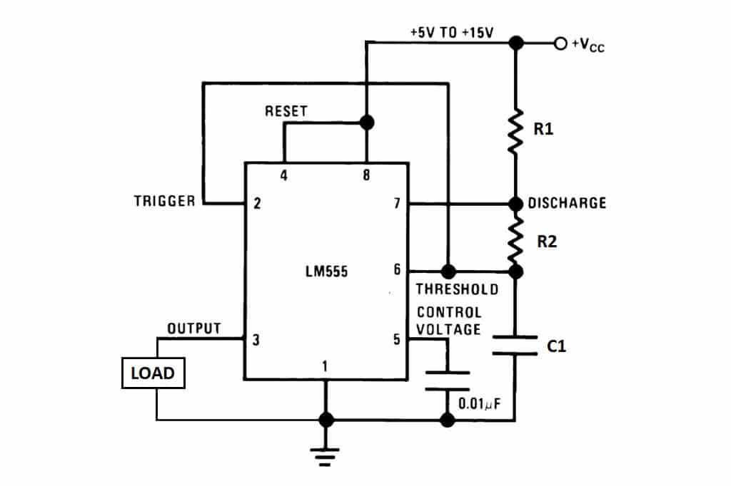
Its name is derived from three 5k ohm resistors,connected in series used in it.the timer ic can produce required waveform accurately. The coil will need to be energized for about 10 seconds. Above schematic diagram shows the 555 timer monostable multivibrator circuit. An added bonus is that these transistors also significantly boost the available output source current above the 555's nominal output. It is used for different purposes such as a timer, delay, oscillator, or pulse generation.
555 timer oscillator from 1.bp.blogspot.com When triggered it will go to its. I used a 9v supply. This tutorial provides sample circuits to set up a 555 timer in monostable, astable, and bistable modes as well as an in depth discussion of wiring info: Monostable multivibrator (mmv) mode of 555 timer ic is also called single shot mode. It is used for different purposes such as a timer, delay, oscillator, or pulse generation. Finally, power up your circuit by connecting the battery to your breadboard The 555 timer is an integrated circuit, it is extremely versatile and can be used to build lots of different circuits. Its name is derived from three 5k ohm resistors,connected in series used in it.the timer ic can produce required waveform accurately.
This article covers every basic aspect of 555 timer ic.
After one timing cycle is completed this circuit doesn't repeat its timing cycle after we push. With this information you will learn how how the 555 works and will have the experience to build some of the circuits below. Ic 555 adjustable timer explained here can be adjusted from any time delay 1 second to 3 hours for for the present adjustable ic 555 timer circuit design we incorporate the second mode of operation i am an electronic engineer (dipiete ), hobbyist, inventor, schematic/pcb designer, manufacturer. If you still need a detailed understanding of the 555 timer. When triggered it will go to its. A monostable 555 timer is required to produce a time delay within a circuit. The coil will need to be energized for about 10 seconds. Think of it this way: As the name indicates, only one state is stable and the other one is called unstable or quasi stable state. The 555 timer is a simple integrated circuit that can be used to make many different electronic circuits. An added bonus is that these transistors also significantly boost the available output source current above the 555's nominal output. The 555 timer could easily be the most common chip used in diy electronics projects because it's small, inexpensive, and very useful. This tutorial provides sample circuits to set up a 555 timer in monostable, astable, and bistable modes as well as an in depth discussion of wiring info:
In the 555 timer block or functional diagram, comparators are those devices which output is high, when their positive input voltage is greater than their negative input voltage and vise it is also known as single shot mode or pulse generating mode. • in the time delay mode, the delay is controlled by • to understand how the capacitor is used in the 555 timer oscillator circuit, you must understand the basic charge and discharge cycles of the capacitor. This article covers every basic aspect of 555 timer ic. The schematic diagram below shows how a 74121 may be wired. The coil will need to be energized for about 10 seconds.
This article covers every basic aspect of 555 timer ic.
If you still need a detailed understanding of the 555 timer. I used a 9v supply. This ic is cheap and is easily available therefore it's commonly. It can be used for various timing. The schematic is shown in fig 5. 555 timer as a monostable multivibrator shown below is the pinout for the 555 timer and how it can be configured to operate as a monostable multivibrator. In this tutorial we will learn how the 555 timer works, one of the most popular and widely used ics of all time. To answer your questions, the relay current is 72ma at 5v or 30ma. Connect power and ground to pins 8 and 1 of the 555 timer (red and black wires). The diode in the triggering circuit is used to clamp the 555's trigger pin to vcc plus one diode drop when the switch is released and the coupling cap is acting like a charge pump. This tutorial provides sample circuits to set up a 555 timer in monostable, astable, and bistable modes as well as an in depth discussion of wiring info: 555 timer was first introduced by signetics corporation in. Simple 555 timer circuits & projects.
After one timing cycle is completed this circuit doesn't repeat its timing cycle after we push. This ic is cheap and is easily available therefore it's commonly. It can be used for various timing. The coil will need to be energized for about 10 seconds. Ic 555 adjustable timer explained here can be adjusted from any time delay 1 second to 3 hours for for the present adjustable ic 555 timer circuit design we incorporate the second mode of operation i am an electronic engineer (dipiete ), hobbyist, inventor, schematic/pcb designer, manufacturer.
555 Timer Basics - Astable Mode from www.circuitbasics.com The 555 timer is an integrated circuit, it is extremely versatile and can be used to build lots of different circuits. I used a 9v supply. As the name indicates, only one state is stable and the other one is called unstable or quasi stable state. The schematic is shown in fig 5. To answer your questions, the relay current is 72ma at 5v or 30ma. It is used for different purposes such as a timer, delay, oscillator, or pulse generation. Think of it this way: A bedside lamp timer circuit schematic.
To answer your questions, the relay current is 72ma at 5v or 30ma.
The schematic diagram below shows how a 74121 may be wired. Simple 555 timer circuits & projects. It's considered a timer because it can output pulses of electrical current for exact amounts of time. You can watch the following video or read the written tutorial below. To answer your questions, the relay current is 72ma at 5v or 30ma. The schematic is shown in fig 5. When vcc > 9v, the base to emitter junction starts to zener and. This tutorial provides sample circuits to set up a 555 timer in monostable, astable, and bistable modes as well as an in depth discussion of wiring info: When triggered it will go to its. Above schematic diagram shows the 555 timer monostable multivibrator circuit. The 555 timer's output will be connected to a micro relay coil. I believe i can use a monostable multivibrator, constructed with a 555 timer. Derivatives provide two (556) or four (558) timing circuits in one package.
In the 555 timer block or functional diagram, comparators are those devices which output is high, when their positive input voltage is greater than their negative input voltage and vise it is also known as single shot mode or pulse generating mode 555 timer schematic. As the name indicates, only one state is stable and the other one is called unstable or quasi stable state.

